Page 1 of 1
Limp mode...
Posted: Sat Jan 20, 2018 3:09 am
by ssf1342
I recently acquired a 1988 635csi auto (build date 5/87) than ran without issues until last week when the transmission electronics light popped on after starting the car. I have a copy of the ETM, but before I dive into further troubleshooting I noticed a few things:
1. AT fluid is clean & appears to be at the correct level.
2. The ETM System Check Table says that the light should flash twice as the ignition is turned to RUN, but it only flashes once. Is this a typo?
3. The Program Selector switch, if set to 321 prior to starting the car, does not switch back to E. It only goes about halfway. 321 does light up on the dash when selected.
4. The transmission shift with a kick when shifting from D to reverse.
5. Kick-down switch does click.
Any ideas on what these symptoms might point to from previous experiences? Is the TCu located behind the driver's side lower dash? When I use realoem to look up parts using the car's VIN, it seems like I get m30B34 parts diagrams instead of those for a m30b35.
Re: Limp mode...
Posted: Sun Jan 21, 2018 1:42 pm
by Pod
You could try disconnecting the battery for a few minutes. It may clear the fault.
Re: Limp mode...
Posted: Sun Jan 21, 2018 10:15 pm
by ssf1342
wfwright2 wrote: ↑Sun Jan 21, 2018 3:02 am
No fix for your transmission, but on my M6 with 5/87 build date, I upped the part look up vin to get a 6/87 build date to get proper parts listing. Seems that the model year build started earlier than officially listed.
Real problem with body parts, especially chin spoiler and brackets.
I ended using my '89 VIN, but I wasn't sure if there were any differences between '88 & '89. For example, for my e34 is has a build date of May 1990, so there are some things that differ from a July 1990 & beyond, like driver's side wiper arm design & some suspension components if I recall correctly.
Re: Limp mode...
Posted: Sun Jan 21, 2018 10:19 pm
by ssf1342
Pod wrote: ↑Sun Jan 21, 2018 1:42 pm
You could try disconnecting the battery for a few minutes. It may clear the fault.
I tried that as I was cleaning the battery terminals & checking out the cables last week. I also did a quick check on the selector switch & cleaned the two connectors. On a visual inspection the wires & connectors seem fine.
Re: Limp mode...
Posted: Tue Jan 23, 2018 3:39 am
by ssf1342
So following the Symptom Table of the ETM, it looks like I need to perform the Engine Speed & Fuel Rate Input Test & Hydraulic Pressure Regulator & Solenoid Test. I am confused about where the specific module(s) is/are located & how to identify the test points.
Re: Limp mode...
Posted: Wed Feb 07, 2018 9:09 pm
by ssf1342
Re: Limp mode...
Posted: Wed Feb 07, 2018 9:21 pm
by ssf1342
Re: Limp mode...
Posted: Sun Mar 04, 2018 2:04 am
by ssf1342
So after finding an ETM for a 1988 635csi, I started over with troubleshooting. Still have the same symptoms (transmission gear light flashes once with ignition to RUN, then stays lit after turning the engine on, car runs only in 3rd gear & reverse). Since my symptoms still indicate testing the Engine Speed & Fuel Rate Input, I had to measure >10V at pins 11 & 21 of the TCU, but I could not figure out how to test specifically at pins 11 & 21 of the TCU, so I measured at pins 8 & 7 on the MCU side of C133 connector. As you can see in the diagram, I measured 12V at pin 7 but 8V at pin 8 on the MCU side of C133. So if the MCU pin 32 is supposed to provide the output of >10V to the TCU pin 11, it would seem that the MCU is bad. However, I switched out the MCU (yellow label ending in 150) with the MCU from my '89 635csi (red label ending in 179), I still had the transmission gear light symptoms. I also checked voltage at C133 pin 1, which measured at 4.74V (close to the approximate 5V at TCU pin 24). You can also see in the diagram other voltages I measured at C133 & the original values at the TCU as indicated in the ETM. My fuel rate gauge does seem to function when I drive the car around the neighborhood. At this point I would like to swap out the TCU with the one from my '89, but I am not sure how to remove the TCU connector.
I haven't had a chance to get underneath the car to check on the connector (to eliminate it as a possibility) that plugs into the side of the transmission; weather & circumstances prohibit it for now.
Re: Limp mode...
Posted: Sun Mar 04, 2018 4:56 am
by Brucey
the first thing you should do is identify what build you really have. I think that a build date of 5/87 would normally mean that you should have a M30B34 engine, but the ...150 ECU is suggestive of the M30B35 motor. This is easily identified because the B34 has bracing struts between the cylinder head and the inlet manifold, as well as crank sensors on the LHS of the bellhousing. The B35 has neither.
I would not recommend that you use wiring diagrams etc from 1989 models because there are small differences. In particular IIRC the transmission control unit changes with build date.
Any parts or wiring that are coloured yellow are almost certainly to do with the airbag system or (rarely) the ABS system (I'm thinking of the sensor connections). Hence the yellow box is an airbag control module. You should take special precautions (as detailed in the workshop manual) when working on any parts of the airbag system.
Troubleshooting the electronically controlled autoboxes is not easy. You can test the inputs to the control unit (speed, throttle opening etc) and make sure that the unit has good power and good ground connections. Then if you can, try a substitute control unit (they sometimes go wrong).
If the gearbox selects some gears and not others it may indicate that the control unit is simply in limp-home mode (3rd and reverse sounds familiar) or it could indicate a fault with some of the solenoid valves inside the transmission.
If you have a B35 motor then you are best off using this ETM (if you don't have it already)
http://wedophones.com/Manuals/BMW/1988% ... Manual.pdf
component locations are shown in the later pages
cheers
Re: Limp mode...
Posted: Sun Mar 04, 2018 5:43 am
by ssf1342
Brucey,
My VIN's last seven is 3266203. Realoem would indicate that I should have a M30B34, but in fact I have a M30B35.
Thank you for the link, but the ETM that I am currently using is the same one & the attachment previously provided is from that.
Another thing that confuses me is that the ETM will say "Measure Voltage at TCU Connector (Connected)" as if there is a breakout panel of test points readily accessible. I can't test pin 11 of the TCU connector if it is still connected, so that is why I test the next viable point at C133.
Re: Limp mode...
Posted: Sun Mar 04, 2018 2:45 pm
by Brucey
it is assumed that you either
a) use a harness adaptor to allow probing or
b) you remove the back of the connector housing to allow access for probing.
IIRC the transmission ECU connector plug is built in a similar way to the connector onto the main ECU; the back comes off this fairly easily to allow probing.
If access is bad and/or you envisage wanting to do lots of tests on certain pins, it makes sense to solder wires onto the relevant pins in the plug, and run these out to a more convenient location.
If the transmission ECU is missing some inputs altogether, or they are intermittent/conflicting, it will trigger the onset of a limp-home mode.
cheers
Re: Limp mode...
Posted: Sun Mar 04, 2018 10:38 pm
by ssf1342
I had no idea that the backs of the TCU & MCU/ECU/DME connectors could be remove to allow access to the pins for testing. Makes sense. Going to give it a try then; is there a trick or special tool needed?
I also see the P/N for the universal adapter connector cables & harness now in the Troubleshooting Hints section of the ETM. $721 from ECS Tuning!

Re: Limp mode...
Posted: Mon Mar 05, 2018 12:21 am
by ssf1342
Correction, MCU/ECU/DME connector cannot be accessed from the back & requires the universal adapter.
Re: Limp mode...
Posted: Mon Mar 05, 2018 9:16 am
by Brucey
ssf1342 wrote: ↑Mon Mar 05, 2018 12:21 am
Correction, MCU/ECU/DME connector cannot be accessed from the back & requires the universal adapter.
mostly they are similarly constructed to this 55 pin one
http://forums.quattroworld.com/s4s6/msgs/212815.phtml
and it is thus easy enough to probe (or solder test leads to) the back of the connector. I have done it several times on various TCUs, ABS control units, engine ECUs etc.
If there are design variants that make this (and, presumably, any repair operations) impossible in this case, do share.
cheers
Re: Limp mode...
Posted: Fri Mar 09, 2018 7:47 pm
by ssf1342
I looked at the TCU connector but could not figure out how to open it up to expose the pins for testing. It has a screw to the right, but it seems access to it is blocked by a black tab of sorts. There's a poor tape job on it & zip ties, so maybe it has been opened up before. There is a seam across the middle of the connector where it looks like the halves can split open.
Re: Limp mode...
Posted: Sat Mar 10, 2018 7:31 pm
by Brucey
there are various ways this connector is assembled but one is depicted in this illustration
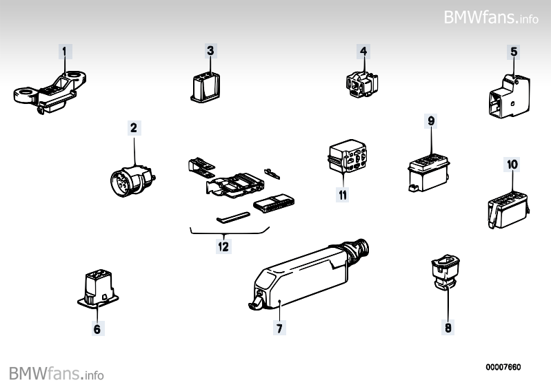
In this variant there is a hook at the thin end of the connector and a sprung latch hidden behind the cable at the fatter end. To remove the connector from the ECU, flick the latch open, pull the cable end of the connector clear, and once it is clear a certain amount the hook end will unhook and this will let the connector come clear of the ecu completely. Then you can cut the zip tie and remove the screw etc to remove the connector's rear cover and allow access to the back of the pins. Sometimes you can do this without removing the connector from the ecu.
Sometimes however you can only easily remove the connector from the ecu if you loosen the bracket that holds it in position, because there simply isn't enough slack in the harness to allow the connector to be removed easily, or there are screws that hold the connector into the ECU (TCU). If in doubt this might be the best way because you will get a good look at the parts and be more sure that you are doing the right thing.
[edit this photo is (I think) of the 4HP22 TCU connector. The latch is on the RHS

]
cheers
Re: Limp mode...
Posted: Sun Mar 11, 2018 1:58 am
by ssf1342
Brucey,
I was able to remove & crack open the TCU connector thanks to your guidance. Following the symptom table again, I started taking measurements & recorded the following for the Engine Spped & Fuel Rate Input Test:
TCU pin 11 = 7.37 V (should be >10 V). Fuel rate gauge does work, so the ETM says to check the wiring to pin 11. It looked fine on the TCU side.
TCU pin 21 = 12 V (should be >10 V, so this is good)
For the Hydraulic Pressure Regulator & Solenoid Test:
TCU pin 1 = 113 kOhm (should be > 500 kOhm)
TCU pins 1 & 25 = 40.3 Ohm (should be 25-46 Ohm)
TCU pins 1 & 20 = 42 Ohm (should be 25-46 Ohm)
TCU pins 1 & 17 = 36 Ohm (should be 25-4 Ohm)
TCU pins 1 & 16 = 35.3 Ohm (should be 25-4 6Ohm)
TCU pins 1 & 22 = 6.3 Ohm (should be 1.8-4.6 Ohm)
What I find odd is that TCU pin 11 should receive an input voltage of >10 V from the Motronic Control Unit but I am measuring less than that at both C133 pin 8 & TCU pin 11. I previously swapped out the MCU & that did not resolve the issue. The resistance readings on TCU pin 1 & pins 1 & 22 are out of specs, so it looks like I will need to find an opportunity to crawl underneath the car to check C152 &/or solenoid-related stuff.
Re: Limp mode...
Posted: Sun Mar 11, 2018 2:23 am
by miklilmag
Hello
I haven't had a chance to get underneath the car to check on the connector (to eliminate it as a possibility) that plugs into the side of the transmission; weather & circumstances prohibit it for now.
[/quote
do this soon!
Good luck,
Franke
Re: Limp mode...
Posted: Wed Jan 09, 2019 6:07 pm
by ssf1342
Update: I had the car towed to an independent shop due to starter issues & I asked them to check out the limp mode issue as well. They drained out some ATF to get the correct level & checked the condition of the transmission connector (which was good). Swapped the 179 ECU back to the original 150; still getting the limp mode light & now a check engine light. The tech said that there was a service bulletin many moons ago where a diode was installed in the transmission wiring harness to protect the ECU from power surges & that this car never had it done. Some questions:
1. Is anyone aware of this service bulletin?
2. Does the 179 ECU (which is from an e32 735i) provide incorrect voltages to the transmission circuit? Because I thought the 179 was compatible with the 150.
3. Is there any difference between the 4hp22-eh that was installed in the various model years of BMWs?
Re: Limp mode...
Posted: Wed Jan 09, 2019 9:23 pm
by ssf1342
SIB 12 07 88 (1678)
Suppression diode harness P/N 88 88 2 000 100
Re: Limp mode...
Posted: Fri Feb 08, 2019 7:30 am
by ssf1342
Turns out the resolution to my limp mode issue was a faulty TCM. Not sure of the cause. Car runs well but I had a high idle (~1k RPM) issue. Adjusted my TPS (6-pin) to hear the "click" & tightened in that position to resolve.
I am still curious if there is any significant difference between the voltage outputs from a 179 MCU/ECU & a 150 ECU going to the transmission circuitry. As far as I can tell the only difference is Motronic 1.1 (150) vs. 1.3 (179). Also this SIB regarding the diode in the harness is a bit concerning if I should ever need to jump start the car.